- Back to Home »
- First-Order Circuits
Posted by : Unknown
Monday, October 14, 2013
Introduction
We have considered three passive elements
(resistors, capacitors, and inductors) and one
active element (the op-amp) individually, Now
will consider circuits that these contains various
combinations of two or three of the passive
elements. We shall examine two types of simple
circuits: a circuit comprising of a resistor and a capacitor
called RC Circuit and a circuit
compromising of a resistor and a inductor called RL Circuit
Source-Free RC Circuit
A source-free RC circuit occurs when its dc source is suddenly disconnected.
The energy already stored in the capacitor is released to the resistors.
Our objective is to determine the circuit response, which, for pedagogic reasons, we assume to be the voltage v(t) across the Capacitor. we can assume that at time t = 0, the initial voltage is:
v(0) = V0
with the corresponding value of the energy stored
This shows that the voltage response of the RC circuit is an exponential decay of the initial voltage. Since the response is due to the initial energy stored and the physical characteristics of the circuit and not due to some external voltage or current source, it is called the natural response of the circuit.
The natural response of a circuit refers to the behavior (in terms of voltages and currents) of the circuit itself, with no external sources of excitation.
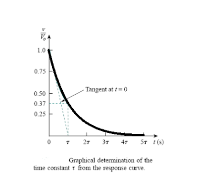
As t increases, the voltage decreases toward zero. The rapidity with which the voltage decreases is expressed in terms of the time constant, denoted by the lower case Greek letter tau, τ.
The smaller the time constant, the more rapidly the voltage decreases, that is, the faster the response.
This is illustrated in A circuit with a small time constant gives a fast response in that it reaches the steady state (or final state) quickly due to quick dissipation of energy stored, whereas a circuit with a large time constant gives a slow response because it takes longer to reach steady state.
At any rate, whether the time constant is small or large, the circuit reaches steady state in five time constants.
THE SOURCE- FREE RL CIRCUIT
Consider the
series connection of a resistor and an inductor, as shown in Figure. Our goal
is to determine the circuit response, which we will assume to be the current i(t) through the inductor. We select the
inductor current as the response in order to take advantage of the idea that
the inductor current cannot change instantaneously. At t = 0, we assume that the inductor has an initial current I0 or
i (0) = Io
with the
corresponding energy stored in the inductor as

Singularity
Functions
Singularity
functions (also called switching functions) are very useful in circuit analysis. Because if we understand singularity
functions, it will help us make sense of the response of first-order circuits
to a sudden application of an independent DC voltage or current source and good
approximations to the switching signals that arise in circuits with switching
operations, it provide a compact description of some circuit phenomena, especially
the step response of RC or RL circuits and functions that are either
discontinuous or have discontinuous derivatives. And the three most widely used
singularity functions in circuit analysis are the unit step, the unit
impulse, and the unit ramp functions.


